
Back to Loco of the Month homepage
Back to Sidestreet Bannerworks
.
January 2008
Bassett-Lowke's gauge-3 Experiment
by Marc Horovitz
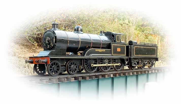
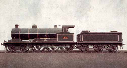
The locomotive after which this model is patterned was designed by George Whale for the London & North Western Railway. It was introduced in 1905 and was the successor to the smaller but highly successful “Precursor” class of 4-4-0s, which had been introduced the previous year. Experiment was intended for passenger work, but it spawned the “Experiment” class of 19" (cylinder diameter) goods engines. The only difference between these latter engines and the original Experiment was that the goods engines had smaller drivers.
The model
In Bassett-Lowke’s earlier days, the company commissioned a lot of its products from other manufacturers. One of the primary suppliers of 2-1/2"-gauge locomotives prior to 1913 was Carson & Co. (James Carson). In 1913, Bassett-Lowke acquired all of Carson’s tooling and continued to make at least some of the Carson range for some time afterwards.
Experiment is one of Carson’s better-known engines and it reflects the high level of commercial model building in Britain at the time. This is a scale model of a specific locomotive, not a toy representation of something it little resembles.
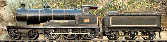
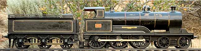
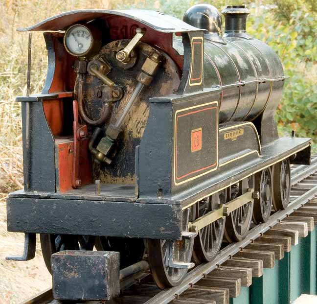
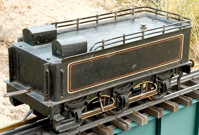
Experiment is a beautiful model. It has a cast-iron cab, footplate, and other parts, while the tender has a cast-iron frame and end beams. The boiler is of the Smithies variety, fired by a massive six-wick alcohol burner with a sump under the cab. Fuel is carried in the tender, which is simply a large tank. A feed tube departs the bottom of the tank , passing through a valve mounted to the left-hand frame. From there, it leads to the sump on the engine. The idea is to adjust the valve on the tender to supply the engine’s needs – no more and no less.
The engine has no pumps, either hand or axle, so must be shut down between runs. There is a check valve on the backhead, but, on my example, it is not plumbed into anything.
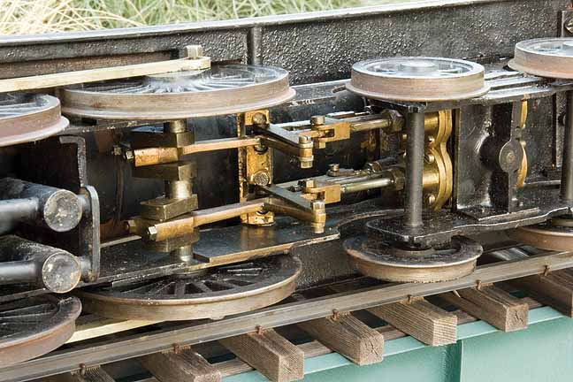
Two inside cylinders drive the leading axle, which can be removed from the frames. The other two axles are trapped in the frames. The chassis is unsprung. Like the prototype, the model has proper Joy valve gear, controlled from the cab. Construction is robust – the engine was designed for operation. Backhead fittings include a throttle, blower, water glass with blowdown valve, and a pressure gauge.
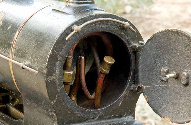
The smokebox door snaps open. Inside are the usual things, including blower and exhaust pipes. There is also a cylinder-lubricator line with a cap on it. I could find no evidence of an actual lubricator reservoir. I surmise that this is a direct line into the cylinders.
When I received the engine, the safety-valve shell was there, but it had no innards. I sent the shell to Rafe Shirley, who kindly made and installed the missing pieces. Aside from that, this old engine is complete and in excellent mechanical condition. It certainly shows signs of use and has that wonderful patina of age on it, all of which adds immensely to its character. As of this writing, I’ve not run it on steam. It runs beautifully on compressed air, though, the throttle giving fine control. I hope one day to run it on steam, but must first give it a proper boiler test.
|
|
|
| Builder | Carson & Co. for Bassett-Lowke Ltd. (UK) |
| Date built | Circa 1910 |
| Gauge | 3 (2-1/2") |
| Scale | 1:24 |
| Boiler | Smithies |
| Fittings | Safety valve, throttle, blower, water glass with blowdown, pressure gauge, check valve |
| Fuel | Alcohol |
| Blow-off pressure | 60 psi |
| Cylinders | Two, double-acting D-valve |
| Reversing gear | Joy |
| Lubricator | Direct feed |
| Weight | 18 lbs., 14 oz. (with tender) |
| Dimensions | Length (loco and tender), 27-3/4"; width, 4-1/4"; height, 6-3/4" |

Back to Loco of the Month home page
Back to Sidestreet Bannerworks home page
This page and its contents
Copyright Sidestreet Bannerworks, 2008
.