Back to Sidestreet Bannerworks
Click here to find out how your engine can be featured!
.

A Midland 1F half-cab
"Project" engine
by Ernie Noa
Monticello, Illinois
Photos by the author
March, 2012
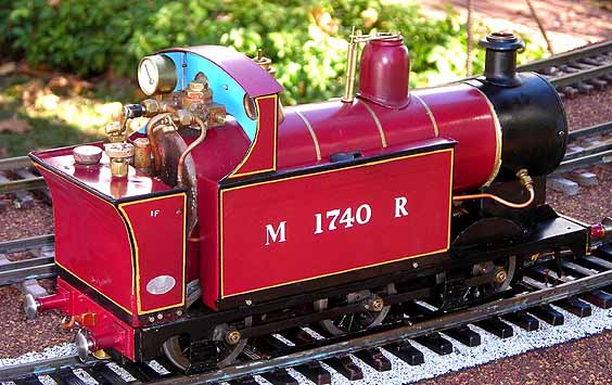
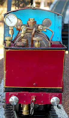
The prototype of the Midland 1F was designed by S.W. Johnson and built in 1878-99. There was a total of 240 built. Some were built with a “half cab.” Mine is a freelance model of the open-cab version.
The model
The model is based on the Gauge 1 Model Railway Association (G1MRA) “Project” engine. This is a set of plans by Ron Poulter and Bob Hines, originally published by the association in 1969. The plans are for a 4F class, which employed a tender. The design calls for a single cylinder.
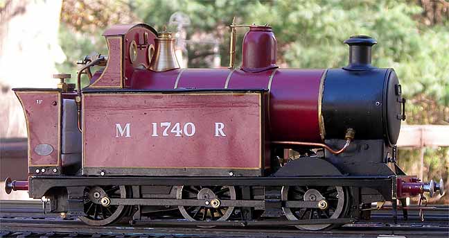
In my model, I deviated several times from the original plans. First, this engine has a 5/8” cylinder, whereas the plans call for a 3/4” cylinder. As originally planned, this was a high-pressure engine intended for fast running. I wanted to tame it down a bit, so my engine was designed to run at around 40 psi and pull just a few cars, as it would have done in real life. I also went with a three flue, type-C boiler versus the project boiler. The lubricator was changed from a pressurized version to a dead leg.
After construction there were the usual problems in getting the engine to run well. Chimney and blast-pipe geometry (1:6 and 1:3) had to be adhered to. The three wicks took some experimenting with to provide an adequate fire.
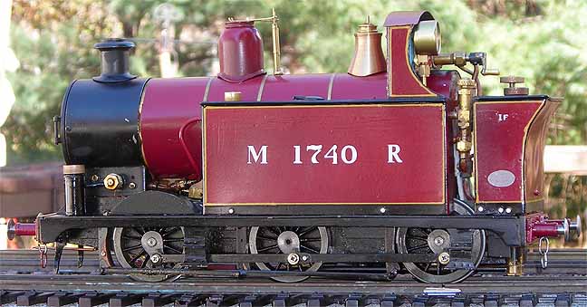
Although it used some commercial parts from Walsall Model Industries (Pressure gauge, wheels, side frames, and cylinder casting), the rest of the parts were all made from bar stock, copper pipe, and recycled material. The smokebox front came from a gas-stove burner – a defunct stove we replaced in the winter of 2009. Another item used was a door kickplate. This provided nice brass/bronze material for the foot plate on either side of the engine, giving the frame lots of stiffness. The steel buffers were turned from some steel rollers from a discarded copy machine. Material for the three flues was left over from plumbing jobs. The boiler wrapper was made from a fuel can, cut up and re rolled for the wrapper. Chains came from a toilet flapper.
The two side water tanks are sealed and soft-soldered together. A balance tube connects them, with the feed in a tee section that goes to the axle pump under the fuel tank. The lubricator is concealed in one of the water tanks.
The engine has a pressure gauge, but no site glass. You can top off the water with a pump bottle. Since it is alcohol fired and the tank is very small, you can also add fuel for a longer run. Run time with one tank of fuel is about 15 minutes. I have had the engine running for over 45 minutes with fuel top offs.
A run
A typical run includes the usual topping off of water, fuel, and oil. The operating cylinder cocks are opened. A suction fan is needed to build up pressure. Since the wicks are up inside the firebox, it is difficult to get them lit but, once they are lit, you can tell, as the fire makes a roaring sound. Steam comes up in about two or three minutes.
With a few cars in tow, the engine handles very nicely, with controlled speed. It runs well at 20 PSI, and that is when I open the regulator. A little push in the forward directions and it makes a "swish-swish" sound from the cylinder cocks. With the cocks closed, the engine takes off on its own. For some reason it is a very quite engine with almost no chuff. It only shows steam out the stack when it is very cold. The lubricator used very little oil, so a more direct line was added and the new lubricator is on the front footplate.
This video was taken at our October 2010 steam up. (If, for some reason, you can't see the video, click here.)
|
|
|
| Builder | Ernie Noa (USA) |
| Date completed | 2009 |
| Gauge | 1 (45mm) |
| Boiler | Type C -- three flues |
| Fittings | Regulator, blower, pressure gauge, safety valve |
| Fuel | Alcohol |
| Cylinders | One double-acting D-valve |
| Reversing gear | Slip eccentric |
| Lubricator | Dead-leg displacement |
| Dimensions | Length, 12-3/4"; width, 3-1/4"; height, 6-1/8" |
| Weight | 7 pounds |

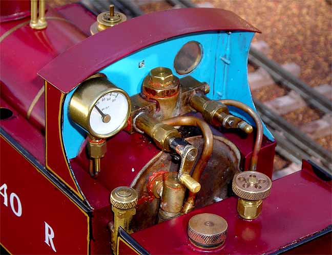
Right: The open cab allows easy access to the controls.

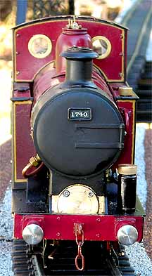
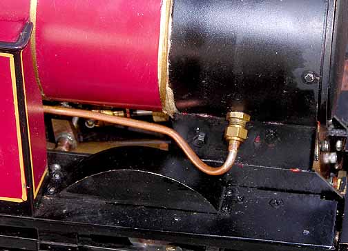
Right: The blower line into the smokebox.
Back to Sidestreet Bannerworks
Click here to find out how your engine can be featured!
This page and its contents
Copyright Sidestreet Bannerworks, 2012